Ps1 Controller To Usb Wiring Diagram Wiring Controller Diagram Usb Ps1
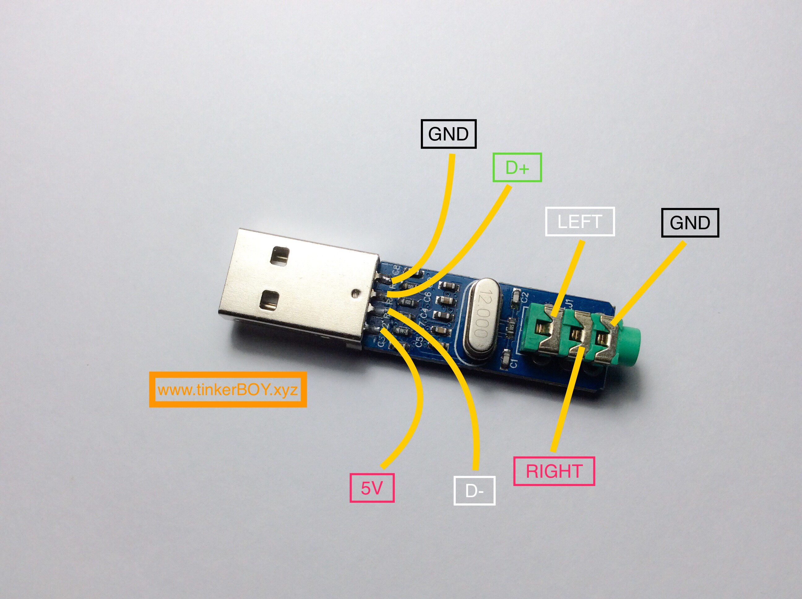
The most popular USB connector, the Type-A, contains four pins: two data pins (D+ and D-) and two power pins (VCC and GND). Power pins power devices, whereas data pins convey data. Printers, scanners, and other power-hungry equipment employ Type-B connectors. It contains five pins: two data, two power, and one ground.
usb socket connection diagram Wiring Diagram and Schematics
The USB bus is a [Differential] Bi-directional serial interface cable bus. Differential NRZI data is transmitted Isochronous or Asynchronous between devices. Data is transferred at one of three different rates over a maximum cable length of 5 meters over 4 wires, 2 of which carry data on a balanced twisted pair.

Micro Usb Cable Wiring Diagram To Rs232
A USB connector is the socket, port, or jack into which the plug end of a USB cable or USB-powered device is inserted. USB connectors are typically female, while the USB plug on the cable is male. Rectangular, slot-shaped USB type-A connectors are most common and can be found on computers, personal electronics, and peripherals.
Wiring Diagram For Split MicroUsb Cable? Electrical Engineering
Flip the plug 180 degrees and the same pins will connect in the same order. Your board should connect both together for maximum connectivity. There is no ID pin, as that's only implemented on plugs. In USB C, the CC pins handle this, and pulling them to ground with a 5K resistor will initiate OTG HOST mode on the other side of the link.

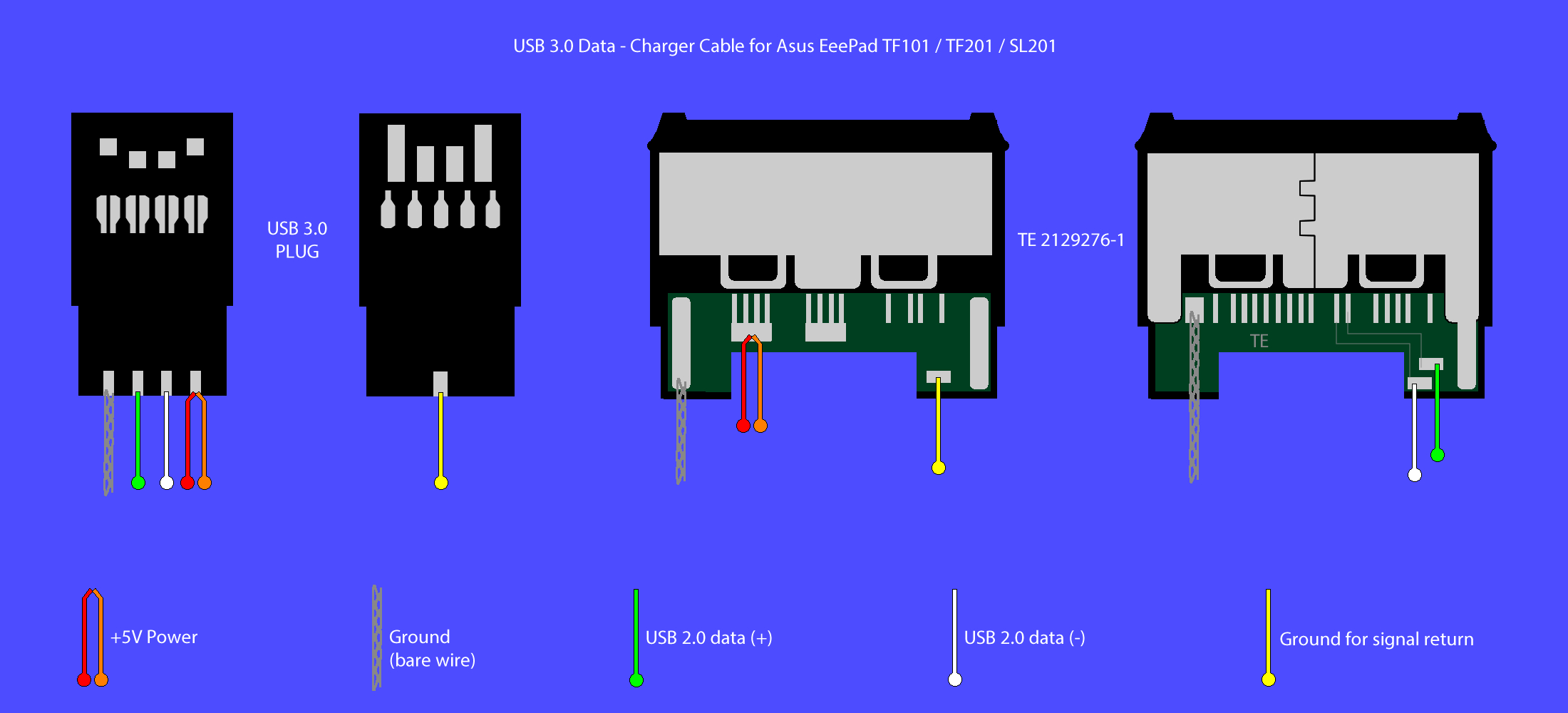
Usb C Port Wiring Diagram Samsung Succ3 Usb Data And Charging Cable
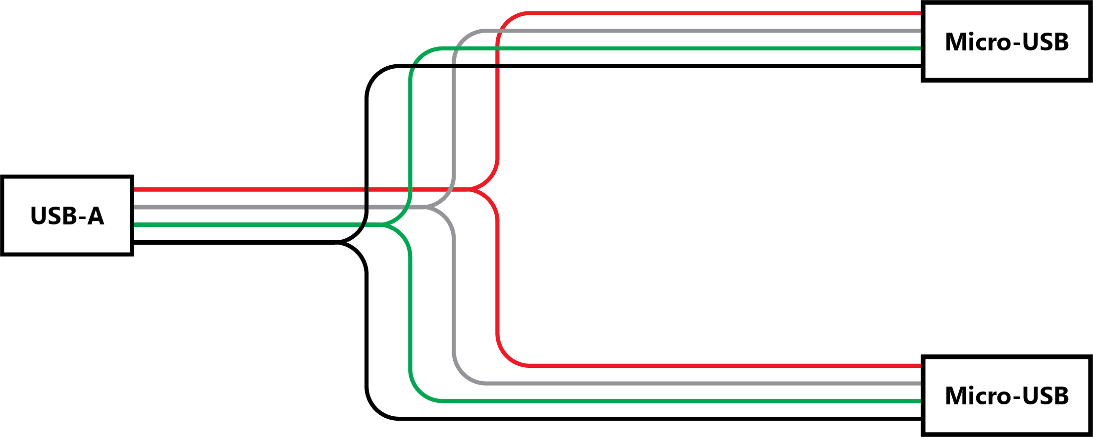
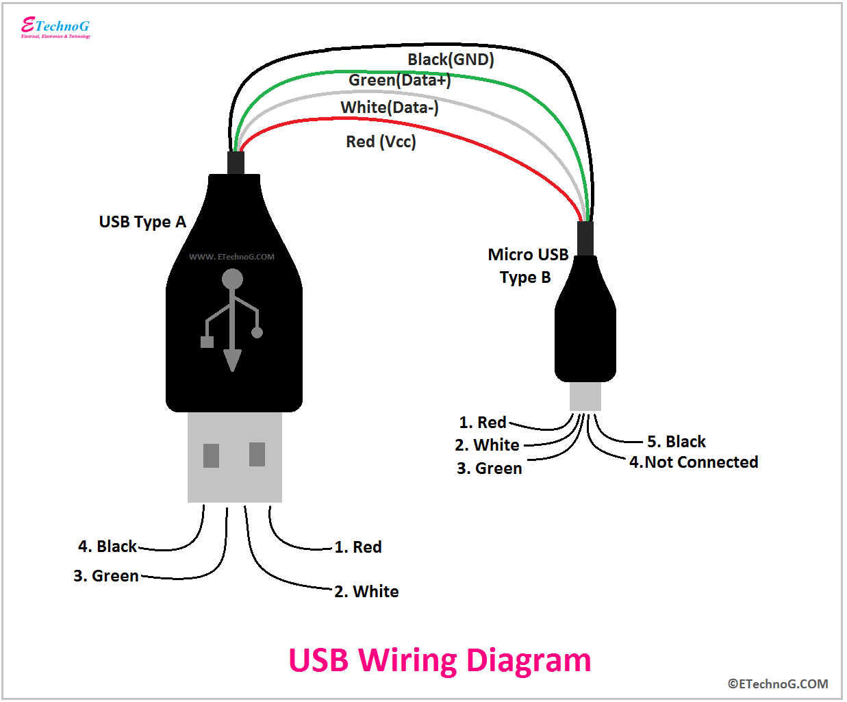
The wiring diagram includes any combination of different types of USB connectors. The most common after USB-type A to USB- type C is "micro USB- type B " to standard " USB-type A " which is generally presents in mobile phone chargers.
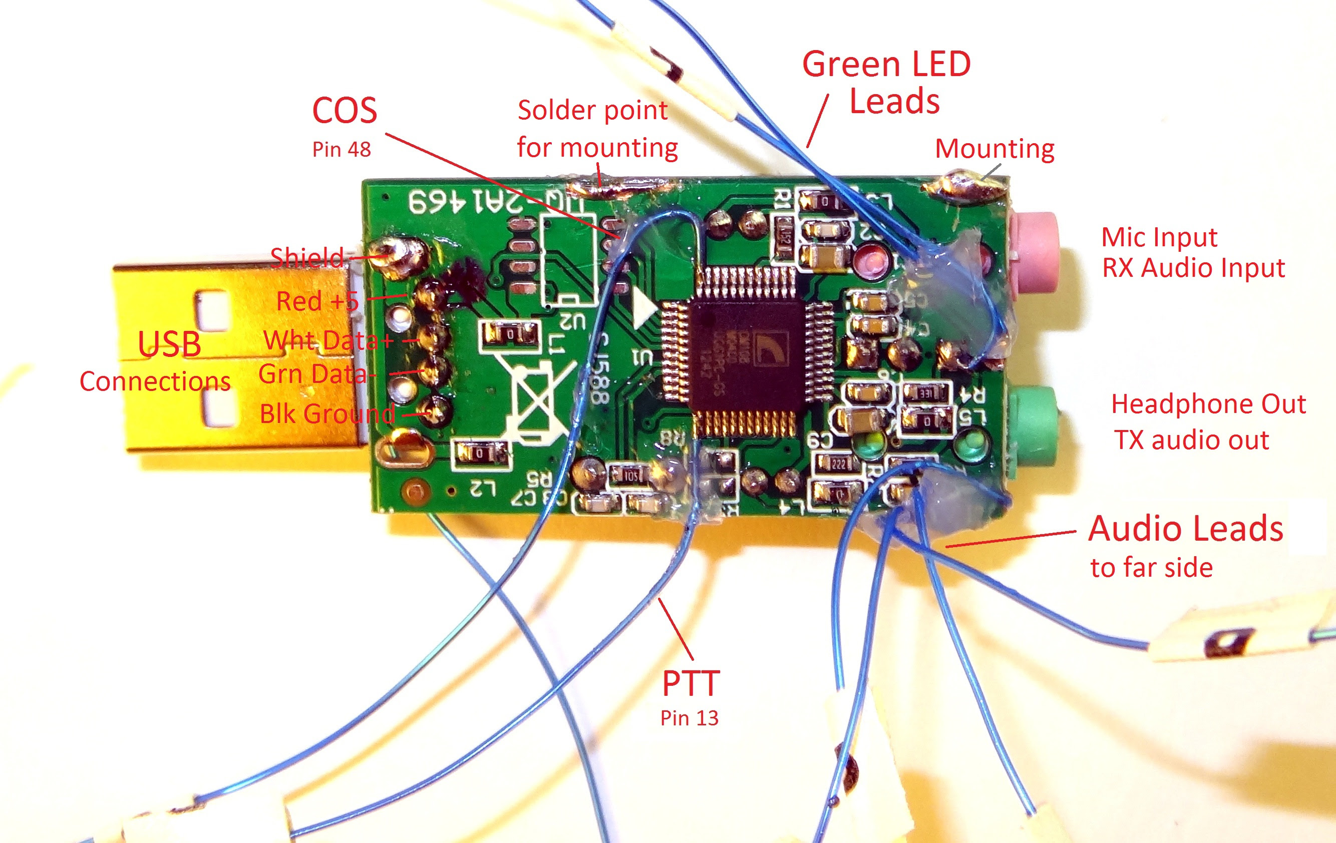
Usb Sound Card Wiring Diagram Ps2 Controller Arduino Wire Playstation
USB pinouts diagram is a graphical representation of the different pins and their functions in a USB connector. It is essential to understand the pinouts diagram when working with USB cables or devices, as it helps in correctly connecting the wires and ensuring proper functionality. 1.
Usb Type A To Micro Usb Wiring Diagram Usb Mini Cable Pinout Charger
Who knows what the future reserves? USB Connections Each USB device uses the standard A type connector to the USB host or Hub through A type receptacle. The other end of the cable has series B connector which is used to plug into the B type receptacle.

USB Wiring Diagram, Connection, PinOut, Terminals ETechnoG
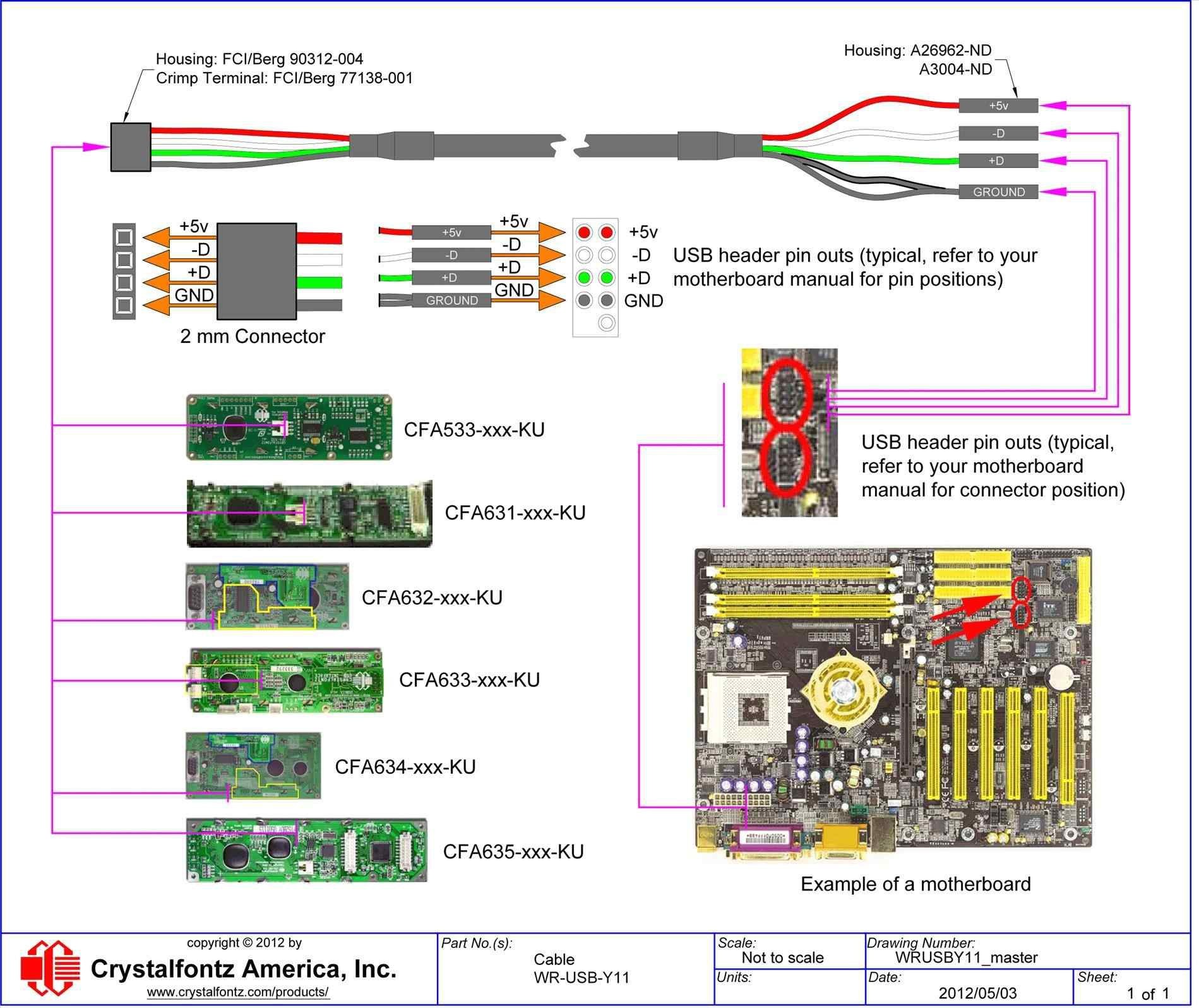
The USB wiring diagram on a motherboard typically includes information about the USB version supported (such as USB 2.0 or USB 3.0), the pin layout for each USB port, and the power and data connections. The diagram may also indicate which ports are capable of charging devices and which ports are for data transfer only.

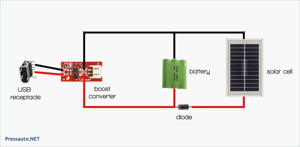
Usb Wiring , Solar Panel Diagram Caravan Solar Panel Kits & Chargers
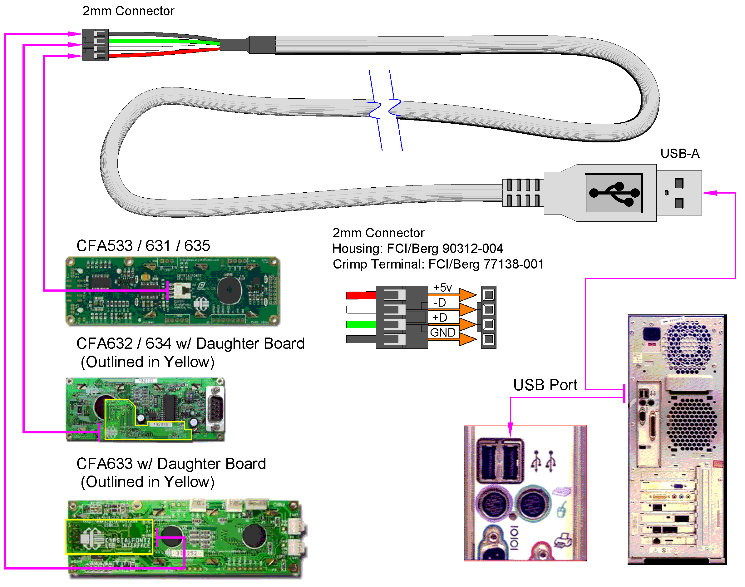
The USB wiring diagram typically involves connecting the power wires (Vbus and GND) and the data wires (D+ and D-) correctly. Incorrect wiring could result in device malfunction or even damage. Additionally, the wiring diagram may also include connections for the shielding wires, which help reduce electromagnetic interference.

Micro Usb Wiring Diagram Pdf Strum Wiring
A wiring diagram is a visual representation of the components used in a circuit. It is like a map that shows the path of electricity between components. A wiring diagram uses symbols to represent each component, such as resistors, capacitors, and transistors. The diagram also includes lines to show the direction of current flow.
Usb C Wiring Diagram Usb Control Board Wiring Diagram Usb Cable Circuit
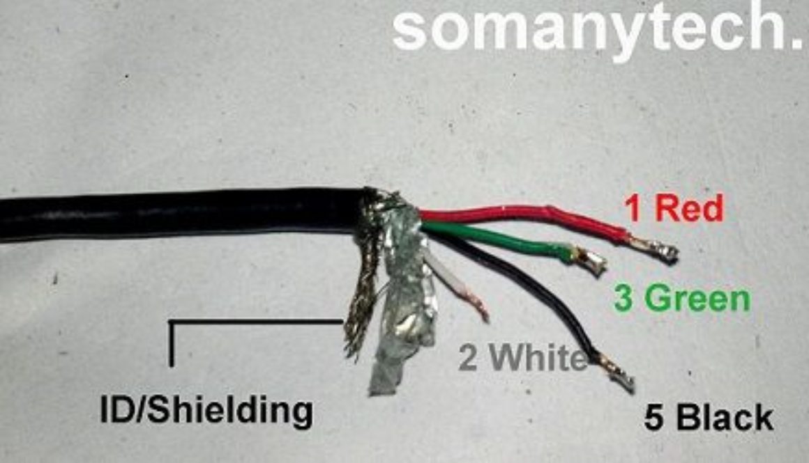
This diagram provides information about the number of wires required, their color code, and the polarity of each wire. It also shows the direction of the wires, which makes it easier to identify which wire is which. A USB cable wire diagram also includes the pin configuration. A USB cable has four pins, which are numbered from 1 to 4.
.jpg)
otváracia výpoveď Let usb c wiring diagram opar trezor site
USB Connector Types: Mini USB Connectors & Pinouts. 19 Nov 2018. USB cables come with five different basic types of USB connector: types A, B, micro B, mini B, and C. The mini connector is common on older non-Apple mobile phones and other portables. However, the USB micro has largely replaced the mini in recent years, and USB-C may soon replace.
multi usb port circuit diagram Wiring Diagram
Very simple. Maximum length of cable is about 5 m for AWG20 and 0.8 m for AWG28 cable. USB D+ and D- are twisted in cable. Outer shell is made of copper braid and aluminum shield. Colors do not mean anything in the wiring scheme. You can use any color wire to rig something. Just make sure the colors match from end to end.
USB Wiring Diagram Power Wiring Diagram
2. USB Wiring Diagram: Understanding the Pins. USB connectors have multiple pins that serve different purposes. The most common USB connectors are Type-A and Type-B. Type-A is typically used on host devices like computers, while Type-B is commonly found on peripheral devices.

Usb To Av Cable Wiring Diagram Rca Vga Wire Diagram For Usb
Table Of Contents USB Type A and Type B Pinout (Male and Female) USB Mini A and Mini B USB Micro A and Micro B USB Standard 3 Features of USB Standard 3 USB Type A 3.0 and Type B 3.0 Micro B 3.0 USB Type C 3.0 The USB pinout can be divided into two parts: USB Connector Pinout and USB port Pinout.
USB Wiring Diagram, Connection, PinOut, Terminals ETechnoG
USB Type B Pinout. The Type B connector has four pins in its older generations and nine pins in standard 3.0: Looking at the Type B connector on a cable, the pins are numbered 1-4, ascending, clockwise from top left in the central rectangular portion of all generations. The third generation adds a row of pins above, numbered 9-5 descending from.